Ruston and Hornsby single cylinder diesel engine type 3XHR


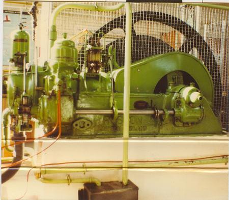
The Ruston and Hornsby 3XHR Single Cylinder Diesel Engine
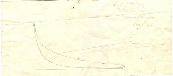
17 bhp
Governed speed 370 rpm
7¼" bore x 13½" stroke
Serial number 297647
This engine was installed in the engines laboratory of the college where I used to work and was disposed of in 1987.

You can hear a recording of it in action below. When it was run for students, it took three people to start it, two to crank it over and the third to drop the inlet valve lifter when it had been cranked up to a suitable speed. But you could just about manage it single-handed as I did here although at the first attempt, the engine didn't fire.

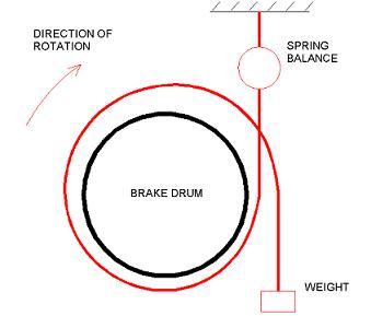
The output power of the engine was measured by a brake. This is a means of applying a load to an engine and in this case it was a heavy rope that wrapped round the brake drum that was fixed at the top end (see below for diagram of the arrangement). The load on the engine was increased by adding weights to the free end. As a result of the brake rubbing on the drum much heat was generated and so the drum was filled with cooling water from a tap to stop the rope catching fire. The water stayed in the drum because of centifugal force and only all fell out, very hot, at the end of the run when the engine came to a stop.

How brake horsepower was measured


This shows how the rope was looped round the brake drum. Knowing the speed of rotation and the torque on the brake drum (spring balance reading minus the weight on the bottom) times (radius of drum)], the
Brake Horsepower could be calculated.

How indicated horsepower was measured

The Brake Horsepower is the power actually appearing at the ouput shaft. To find out how much power is lost in the engine and see how efficient the engine is, we can measure the power being developed by the burning of the fuel in the combustion chamber, the Indicated Horsepower. You can also calculate the power that should be available given the fuel consumption and the calorific value of the fuel.

Indicated Horsepower = area of PV loop x no of cylinders x number of cycles per second not forgetting of course that a four stroke cyle has one power stroke every two revs. This is the indicated horse power or IHP.

We need two pieces of kit to do this. Firstly an engine indicator which will give us an indicator diagram and secondly a planimeter.
The engine indicator is a device for obtaining a diagram of the pressure variation in the combustion chamber while the engine is running.. The indicator shown on the right is actually a steam engine indicator but the idea is exactly the same. This one looks like its been cobbled together from two different ones and there are some parts missing.

The string on the left is connected to the crankshaft so that the drum with the paper on rotates backwards and forwards with each rotation.

The steel bar which the indicator is standing on is where there would be a valve that lets the pressure in the combustion chamber into the indicator.

The special waxed paper is wound tightly round the drum as shown.

When you're ready to make an indicator diagram and the engine is running under the desired conditions, connect the string to the crankshaft output and open the valve to admit the combustion chamber gases to the indicator.
The drum is now banging back and forwards and the pointer (indicated by red dot on picture) is shooting up and down.

Now, without getting your fingers chopped off, swing the pointer (red dot) into contact with the paper and your indicator diagram is made.
This is an actual indicator diagram taken from the above engine during a test. You can just about make out written on it 'Load 70kg, 370 rpm, spring rate 1bar/mm'. The spring rate says that for every vertical millimetre the pressure inside the cylinder is 1 bar.
The planimeter is a mechanical device for measuring area. This is what will enable us to find the area of the indicator diagram and thus calculate the indicated horsepower.

(1) You put down the blob of metal on the end of the arm shown in the lower left hand corner so it won't move (It has a spike underneath)

(2) Put your drawing the area of which you want to find anywhere close by as shown, in this case our indicator diagram.

(3) Move the pointer on the end of the right. hand arm completely round your diagram once.

(4) The area is indicated on the white dials on the upper end of the picture. Simple., no batteries, electronics or computers - perfect.